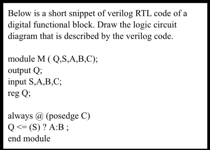
Rtl Code Verilog / Solved Below Is A Short Snippet Of Verilog Rtl Code Of A Chegg Com - Code is any code that is synthesizable is called rtl code.
Get link
Facebook
X
Pinterest
Email
Other Apps
Rtl Code Verilog / Solved Below Is A Short Snippet Of Verilog Rtl Code Of A Chegg Com - Code is any code that is synthesizable is called rtl code.. Nov 16, 2013 #3 g. Harsha perla different ways to code verilog: Let us start with a block diagram of. Verilog code for basic logic components in digital circuits 6. Having completed your verilog coding the next step which you all know is to simulate it and verify if the design is working fine.
So testbench need clock with different phases some other need clock generator with jitter. Since it is the behavioral modeling, we will declare the output y as reg while the rest of the inputs as wire. Once the rtl design is ready, it is easier to convert it into actual hdl code using languages such as verilog, vhdl, systemverilog or any other hardware description language. Hi guys, long time now. After synthesizing, five of them gave same rtl level circuit in xilinx project navigator.
Demystifying Resets Synchronous Asynchronous Oth Community Forums from forums.xilinx.com Cic training manual hdl coding hints: Verilog functions are used to simplify coding in presence of lengthy, complex and repetitive code. Verilog and system verilog are programming languages designed to code hardware at register transfer level. Module m41 ( input a, input b, input c, input d, input s0, s1, output out); Once the rtl design is ready, it is easier to convert it into actual hdl code using languages such as verilog, vhdl, systemverilog or any other hardware description language. Systemverilog assertions (sva) form an important subset of systemverilog, and as such may be introduced into existing verilog and vhdl design flows. Joined oct 18, 2013 messages 87 helped 1 reputation 2 reaction score 1 trophy points 8 activity points 512 rberek said: If you want to learn how to run the simulation without a verilog testbench.
As any verilog code, we start by declaring the module and terminal ports.
Verilog code for fifo memory 3. Verilog was developed to simplify the process and make the hdl more robust and flexible. Having completed your verilog coding the next step which you all know is to simulate it and verify if the design is working fine. Plate license recognition in verilog hdl 9. Module and_2_behavioral (output reg y, input a, b); // wait 100 ns for global reset to finish #100; Systemverilog assertions (sva) form an important subset of systemverilog, and as such may be introduced into existing verilog and vhdl design flows. Once the rtl design is ready, it is easier to convert it into actual hdl code using languages such as verilog, vhdl, systemverilog or any other hardware description language. Plate license recognition in verilog hdl 9. After synthesizing, five of them gave same rtl level circuit in xilinx project navigator. Instead, the output follows input as long as it is asserted. Harsha perla different ways to code verilog: Verilog allows us to design a digital design at behavior level, register transfer level (rtl), gate level and at switch level.
Design at the rtl level is typical practice in modern digital design. Therefore, rtl is also commonly referred to as dataflow design. If the rtl is in verilog, the clock generator is written in verilog even if the testbench is written in other languages like vera, specman or systemc. Verilog code for 2:1 mux using behavioral modeling. Generate the rtl schematic for the sr flip flop.
Solved Below Is A Short Snippet Of Verilog Rtl Code Of A Chegg Com from media.cheggcdn.com Using systemverilog assertions in rtl code. Verilog code for clock domain crossing. Verilog function declaration and call. Having completed your verilog coding the next step which you all know is to simulate it and verify if the design is working fine. Generate the rtl schematic for the sr flip flop. Verilog code for 2:1 mux using behavioral modeling. // wait 100 ns for global reset to finish #100; :) this post is to completely understand and analyze the rtl code which includes the rtl schematic and the technology schematic.
Architectural design of data router in verilog.
Having completed your verilog coding the next step which you all know is to simulate it and verify if the design is working fine. Well, let's move to the main point as the title of this post suggests. Module and_2_behavioral (output reg y, input a, b); Programmable digital delay timer in verilog hdl 5. Therefore, rtl is also commonly referred to as dataflow design. Verilog function declaration and use in rtl code example. Generate the rtl schematic for the sr flip flop. Rtl is an acronym for register transfer level. Clock can be generated many ways. // add stimulus here #100; Plate license recognition in verilog hdl 9. A latch does not capture at the edge of a clock; Systemverilog is a set of extensions to the verilog hardware description language and is expected to become ieee standard 1800 later in 2005.
Therefore, rtl is also commonly referred to as dataflow design. After synthesizing, five of them gave same rtl level circuit in xilinx project navigator. This implies that your verilog code describes how data is transformed as it is passed from register to register. Using systemverilog assertions in rtl code. Now, it's time to run a simulation to see how it works.
Rtl Coding For Fpga Speaker Tsungyi Wu Verilog from slidetodoc.com If the rtl is in verilog, the clock generator is written in verilog even if the testbench is written in other languages like vera, specman or systemc. Module m21 ( d0, d1, s, y); A circuit consists of sequential & parallel events. Verilog function declaration and call. Programmable digital delay timer in verilog hdl 5. Following block diagram can used to implement clock domain crossing for phase offset clocks in digital design. Harsha perla different ways to code verilog: Hdl and verilog are explained in the next section.
Verilog code for 2:1 mux using behavioral modeling.
Rtl is verilog code.you don't draw it, you write it. Verilog code for i2c with rtl schematic. Module m21 ( d0, d1, s, y); Verilog was developed to simplify the process and make the hdl more robust and flexible. This implies that your verilog code describes how data is transformed as it is passed from register to register. Let us start with a block diagram of. Verilog code for basic logic components in digital circuits 6. The biggest surprise to my readers in this post is that this i2c has an rtl schematic. Module m41 ( input a, input b, input c, input d, input s0, s1, output out); Verilog for design training that will show you how to write efficient, accurate rtl code for synthesis & basic testbenching/verification techniques. Following block diagram can used to implement clock domain crossing for phase offset clocks in digital design. The digital hardware consists of concurrent and sequential events. Systemverilog is a set of extensions to the verilog hardware description language and is expected to become ieee standard 1800 later in 2005.
Some testbenchs need more than one clock generator rtl code. If the rtl is in verilog, the clock generator is written in verilog even if the testbench is written in other languages like vera, specman or systemc.

Comments
Post a Comment